Driving ED060SC4(LF) E-Ink Screens
A while back I was struck with the idea to make a low-power, solar-driven e-ink display with WiFi connectivity, so that I could hang it in a window and have information periodically update on it. In particular, an immediately useful function it could perform was showing the weather forecast (forecast accuracy aside). It turns out that these displays, while very easy to acquire due to the popularity of Amazon Kindles, are a bit tricky to drive. In particular, there aren't any publicly-available documents that detail how they work with enough information to get exactly what you want on the screen.
I may have subsequent posts detailing the whole project, but here I want to specifically describe driving the ED060SC4 e-ink display. These are really great displays, since you can get them for ~$15 on eBay (but lately they've been going for more like $30), but feature a relatively high 800x600 resolution. Compare this with some other e-ink displays from electronic hobby shops such as AdaFruit, and you see the attractiveness. Of course, those e-ink displays come with drivers and/or directions, but they are much more expensive for much less resolution.
Prior Work
While there are no reference documents of sufficient detail, I wasn't the only one who had this idea. In particular, the excellent posts by Essential Scrap and Sprite's Mods were invaluable in my efforts to get the display working.
I found that the directions for driving waveforms on Essential Scrap didn't quite work for my display(s), but Sprite's Mods seemed to illuminate the possible cause: there are a number of variants of these displays which sometimes are mislabelled under the same name. They do operate similarly, but what's necessary to drive them correctly tends to differ.
Sprite's Mods also mentions Essential Scrap as a source of inspiration, but found the same issue I did with one of their displays: it simply wasn't working as it should have. Luckily, the author had a device that interfaced with the display, as well as a logic probe, handy, and was able to reverse engineer the signals.
Driving the Display
After following the guidance in Essential Scrap and Sprite's Mods, I still could not get my display to work. I found that the FPC connector was very finicky, and putting different pressures or stresses on it affected the signals. I still need to investigate if proper shielding would resolve the issue. For now, I have it fixed with regard to the rest of the circuit.
Voltages
These displays need 6 different voltages (in relation to a ground voltage): +22V, +15V, -15V, -20V, 3.3V (logic), and a variable voltage, usually between -2V and 0V, to control bias (contrast). Using a few switching voltage regulators, with appropriate circuits to get the desired voltages, did the trick for me. I power everything off of a 3.7V LiPo battery that's charged from a solar cell, so I based my voltage circuits on that.
Wiring/Pinout
I recommend reading Essential Scrap and Sprite's Mods for more details, but the pinout provided on page 6 of the (limited) datasheet was correct. In particular, the final pinout that worked for me looks like:
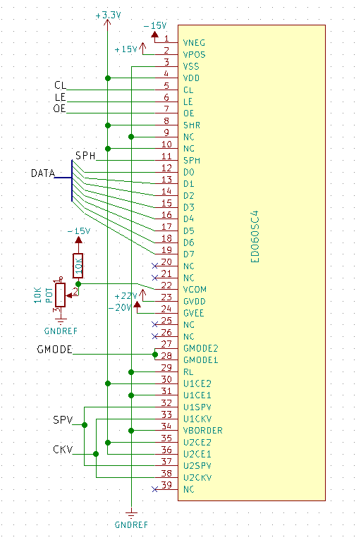
Note that, while the pinout in the datasheet shows NC (not connected) for pins 9 and 10, Sprite's Mods found that they should be connected, so I connected them as well.
Logic
All logic should be driven with 3.3V levels. In total, I used 15 GPIO pins to interface with the display, and 2 more to turn the driving voltages on and off. I used a spare Atmega328P to drive the display.
I broke up the interface for driving the display into 6 distinct steps: power on, power off, start frame, end frame, write row, and (although unused) skip row.
Pin Defaults
I found that starting with SPV and SPH high, and all other pins low,
worked. I did not experiment much with this, but SPV and SPH are
active-low, so it seemed the right thing to do.
Timings
It's worth a quick aside to mention that the some of these signals, like CKV
and CL, had some timing specifications in the datasheet. However, you
won't see them in my code, because the clock rate of the AVR MCU I was using was
such that those timing specifications are met by the timing between the
execution of instructions (typically these timing requirements were on the order
of 10's of microseconds). So when you see clear(CKV) followed immediately by
set(CKV), the timings work out because of the clock rate.
Power On
Page 11 of the datasheet specifies certain timings for voltages that are needed for the display to work. In practice, I found that disregarding or lessening these timings had no immediate ill-effects, but in the interest of preservation, I suggest you follow them.
The power on sequence requires that the negative voltages (-20V and -15V) come
online a millisecond before the positive voltages (+15V and +22V) do. It also
requires that the negative voltages be applied 0.1ms after logic has been
supplied. After that, the OE (output enable) pin should be set high. So the
power on procedure looks like:
void power_on() {
    delay_us(100); // Just in case, only needed if logic power to the display was off
    set(POWER_NEG)
    delay_us(1000);
    set(POWER_POS)
    set(OE);
}
Power Off
Power off doesn't require any particular timings. You essentially just undo
what the power on procedure did, and drop CKV (vertical/row clock) low in case
it isn't low after previous frames.
void power_off() {
    clear(POWER_NEG | POWER_POS | OE);
    clear(CKV);
}
Start Frame
To start a frame, you set GMODE (gate mode/output enable) high, and then set
CKV high (the display reads various values on the rising edge of CKV). Then
LE should be set low (if not already low). CKV should be toggled low then
high (to get that rising edge) while SPV is low, and then SPV should be
returned to the high state.
Finally, I found that my display had some logical 'dummy' rows, so to get the first written row to be the first row of the display, I actually had to skip 3 rows at the start of the frame. YMMV; it might be due to some mistake I'm making elsewhere.
While other guides/code sources had delays in the frame start procedure, I found that no delays were necessary (through experimentation). I also found that rearranging some of these operations still worked!
void start_frame() {
    set(GMODE);
    set(CKV);
    clear(LE);
    clear(SPV);
    clear(CKV);
    set(CKV);
    set(SPV);
}
Write Row
After starting a frame, 600 rows, each with 800 pixels of information, need to
be sent. Each row is started by pulling SPH (start pulse horizontal) into the
active low state. Then the data should be clocked in on the DATA line by the
rising edge of CL (so typically you want to toggle it high and then low
again), 4 pixels at a time (each pixel taking 2 bits of DATA). To send a black
pixel, its 2 bits should be 01, and to send a white pixel, the bits should be
10. 00 and 11 make no change to the pixel. In total, CL should be pulsed
200 times, each with 4 pixels of data, to read 800 pixels for the row.
Once all the data has been clocked in, SPH should be set high to disable data
input. Then CL should be toggled high then low so that SPH is read. Then,
LE should be toggled high then low, and CKV should be toggled low then high,
and finally OE should be toggled low then high. I found all these steps
necessary; omitting or rearranging them resulted in the display not working. I
believe the toggling of OE is what moves the latched data into the row.
void write_row(char* data) {
    // Start row
    clear(SPH);

    // Clock in data
    for (int i = 0; i < 200; i++) {
        DATA = data[i];
        set(CL);
        clear(CL);
    }

    // Latch data and end row, writing to the display
    set(SPH);

    set(CL);
    clear(CL);

    set(LE);
    clear(LE);

    clear(CKV);
    set(CKV);

    clear(OE);
    set(OE);
}
It's worth noting that my implementation was more efficient by assuming you always wanted to set or clear a pixel, and using a 100-byte array to store the 800 pixels for the row. The code here is pseudo-code-like for clarity.
Skip Row
Skipping a row is pretty simple. You just need to pulse CKV down and back up
(this is what is actually moving the active row in the display). Essential
Scrap found that some timing was needed to prevent bleeding (although that was
a different display), but I haven't experimented with skipping rows enough to
comment.
void skip_row() {
    clear(CKV);
    set(CKV);
}
End Frame
Once CKV has been pulsed down and up 600 times (or a few more in the case of
my display, where I found some hidden lines), the frame needs to be ended. This
is quite simple, just bring GMODE back low and pulse CKV.
void end_frame() {
    clear(GMODE);
    clear(CKV);
    set(CKV);
}
Summary
I hope this gives enough guidance and direction to those of you who are trying to use these displays! Once you get it working, they open up a lot of possibilities. I still have some physical connection issues, but hope to resolve them by creating a PCB and housing for my project.
I'm not posting my exact code since, while it is modular and separated from the rest of the project code, it still makes assumptions about system timing and IO pins being used, let alone the host MCU system. So I don't think it's particularly useful to share in that form.
Comments